
KRC Horizontal Boring Mill (HBM) Series
KRC's HBM Series offers the latest in horizontal boring precision and performance.
- Design Flexibility – The KRC HBM Series is a full line of table type and floor type Horizontal Boring Mills made to support a wide range of applications for machining large, heavy-duty workpieces. Built for extreme-duty roughing and high precision finishing, these horizontal boring mills offer modular designs and flexibility to meet the demands of various processes.
- Superior Rigidity and Stability – The main structural components of these machines are made with high-quality alloy castings made according to Meehanite process and a heavily ribbed design allowing for maximum rigidity, vibration dampening and thermal stability.
- Incredible Accuracy and Speed – The hydrostatic guideways allow for incredible accuracy and speed, work-piece finish for longer tool life, and stiffness and durability.
- Customizable – All models can be custom configured in various machine styles, heads, control systems, travel specifications and performance options providing a highly versatile machine tool to meet your application demands.
HBM T-Series

HBM F-Series

KEY FEATURES
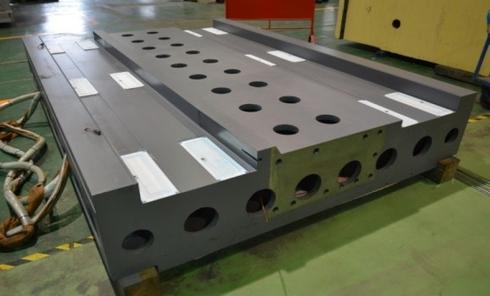
HYDROSTATIC GUIDEWAYS
Hydrostatic guideways can compensate for forces resulting from weight, machining and acceleration. These ways are ideal for horizontal applications, where machining and acceleration forces are lower than the weight forces on the pockets. The result of a hydrostatic way system includes better dampening characteristics, no vibration, minimal wear due to zero contact of surfaces, and no stick slip.
COMBINATION BOX WAY SYSTEM FOR Y-AXIS
The Y-axis is equipped with a combination way system consisting of a box way with low friction material opposite tychoway bearings on hardened steel. The design provides the rigidity and dampening of sliding type box ways and the high accuracy contouring of bearing type guideways resulting in long term durability and reliability.
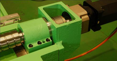
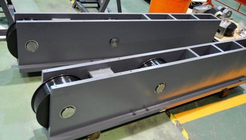
HYDRAULIC COUNTERBALANCE SYSTEM
The column features a hydraulic counterbalance system designed to provide power loss back up and improved axis performance. An advantage of this design provides oscillation free movements from feed rates thru rapid traverse rates. This system helps to maintain a level machine head when either the ram or spindle is extended or an accessory head is utilized.
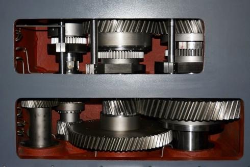
3 STEP GEARBOX HEADSTOCK DESIGN
The headstock design features a modular 3 step gearbox which generates high torque, high speed and high horsepower for efficient part processing. The 3 step gearbox is designed and positioned for easy removal as a unit without disassembling the ram and spindle unit. The gearbox design also provides near constant power from base speed allowing the use of optimum cutting parameters.
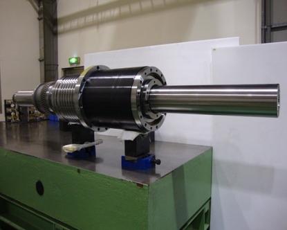
PATENTED SPINDLE DESIGN
The patented spindle design features the best dynamic performance available. Designed with a roller and ball bearing arrangement, the spindle has a hard nitrided surface and travels in a tempered steel sleeve for maximum support, rigidity and long wear. The spindle length is the shortest in the industry with equal w-axis travel. This allows for high rigidity, higher speed and increased accuracy.
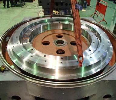
HYDROSTATIC ROTARY TABLE DESIGN
| Bearing | Crossed Roller or Hydrostatic Bearing improves rigidity and accuracy |
| Drive | Dual pinion with split worm transmission |
| Split worm anti-backlash | Hydraulic preload vs. typical spring preload Automatic adjustment |
HBM SPECIFICATIONS
| KRC FHB | Specifications | Unit | HBM-16F | HBM-20F | HBM-26F |
|---|---|---|---|---|---|
| Spindle Head | Boring Spindle Diameter | mm (inch) | 165 (6.47) | 200 (7.87) | 260 (10.24) |
| Spindle Taper | ISO 50 | ISO 50/60 | ISO 50/60 | ||
| Max Spindle Speed | RPM | 3,150 | 2,000 | 1,600 | |
| Spindle Power | kW (HP) | 71 (95) / 88 (118) | 100 (134) / 126 (169) | 130 (174) / 161 (216) | |
| Max Torque | Nm (Ft Lb) | 10,000 (7,376) / 12,400 (9,146) | 18,000 (13,280) / 22,600 (16,670) | 25,000 (18,8440) / 30,900 (22,790) | |
| Machine Travels | Column Travel (X-Axis) | mm (inch) | 3,000 (118) + N ° x 1,000 (39.4) | 4,000 (157.5) + N ° x 1,000 (39.4) | 6,000 (236.2) + N ° x 1,000 (39.4) |
| Spindle Head Travel (Y-Axis) | mm (inch) | 2,000 (78.7) to 4,000 (157.5) | 2,500 (98.4) to 5,000 (196.9) | 3,000 (118.1) to 7,000 (275.6) | |
| Ram Travel (Z-Axis) | mm (inch) | 1,200 (47) | 1,500 (59) | 1,800 (80) | |
| Boring Spindle Travel (W-Axis) | mm (inch) | 1,000 (39.4) | 1,250 (49) | 1,500 (59) | |
| Boring Spindle & Ram Travle (Z + W Axis) | mm (inch) | 2,200 (86.6) | 2,750 (108.3) | 3,300 (1300) | |
| X, Y Rapid Travels | mm/min (IPM) | 16,000 (630) | 12,000 (472) | 10,000 (394) | |
| Z, W Rapid Travels | mm/min (IPM) | 10,000 (394) | 10,000 (394) | 10,000 (394) | |
| Rotary Table | Table Size | mm (inch) | 2,000 (78.7) x 2,000 (78.7) | 2,500 (98.4) x 2,500 (98.4) | 3,000 (118) x 3,000 (118) |
| Max. Table Load | kg (lb) | 20,000 (44,040) | 30,000 (66,060) | 40,000 (88,080) | |
| Machine Dimensions | Machine Weight | kg (lb) | 75 (165,300) | 90 (198,400) | 110 (242,500) |
| KRC THB | Specifications | Unit | HBM-13T | HBM-16T |
|---|---|---|---|---|
| Spindle Head | Boring Spindle Diameter | mm (inch) | 130 (5) | 165 (6.5) |
| Spindle Taper | ISO 50 | ISO 50 | ||
| Max Spindle Speed | RPM | 4,000 | 3,150 | |
| Spindle Power | kW (HP) | 37 (50) / 46 (62) | 51 (68) / 68 (91) | |
| Max Torque | Nm (Ft Lb) | 2,500 (1,844) / 3,100 (2,286) | 4,150 (3,061) / 5,500 (4,057) | |
| Machine Travels | Table Travel (X-Axis) | mm (inch) | 2,000 (78.7) | 2,500 (98) |
| Spindle Head Travel (Y-Axis) | mm (inch) | 1,600 (63) | 2,000 (78.7) | |
| Column Travel (Z-Axis) | mm (inch) | 1,250 (49) | 1,500 (59) | |
| Boring Spindle Travel (W-Axis) | mm (inch) | 750 (29.5) | 1,000 (39.4) | |
| X, Y, Z Rapid Travels | mm/min (IPM) | 20,000 (787) | 16,000 (630) | |
| X, Y, Z Increased Rapid Travels | mm/min (IPM) | 25,000 (984) | 20,000 (787) | |
| W Rapid Travels | mm/min (IPM) | 10,000 (394) | 10,000 (394) | |
| Table Specifications | Table Size | mm (inch) | 1,250 (49) x 1,600 (62) | 1,600 (63) x 2,000 (78) |
| Max. Table Load | kg (lb) | 10,000 (22,020) | 20,000 (44,040) | |
| Rotary Table Specifications | Table Size | mm (inch) | 1,250 (49) x 1,600 (62) | 1,600 (63) x 2,000 (78) |
| Max. Table Load | kg (lb) | 10,000 (22,020) | 20,000 (44,040) | |
| Machine Dimensions | Machine Weight | kg (lb) | 45 (99,210) | 55 (121,300) |
Contact Us
Many clients rely upon KRC Machine Tool Solutions because we overcome difficult challenges with sound, simple results. We’ll meet your timeline and surpass your objectives. Contact us for more information about our specialty machine solutions.
